Engineering Drawing Multiple Choice Questions Pdf Download in Hindi
What is the dimension of A1 size drawing sheet?
- 1189 mm × 841 mm
- 594 mm × 841 mm
- 1230 mm × 880 mm
- 880 mm × 625 mm
Answer (Detailed Solution Below)
Option 2 : 594 mm × 841 mm
Win over the concepts of Engineering Drawing and get a step ahead with the preparations for Basic Science and Engineering with Testbook.
Explanation:
Dimensions in "mm" for different sizes of drawing sheets are as follows:
| Paper Sizes | Dimension (mm × mm) |
| A0 | 841 × 1189 |
| A1 | 594 × 841 |
| A2 | 420 × 594 |
| A3 | 297 × 420 |
| A4 | 210 × 297 |
| A5 | 148 × 210 |
In Engineers scales, designation M5 indicates the scales ____________
- 1 : 200
- 1 : 10
- 1 : 50
- 1 : 400
Answer (Detailed Solution Below)
Option 1 : 1 : 200
Explanation:
Scales are used to make drawings of the objects to the proportionate size desired.
A scale is defined as the ratio of the linear dimensions of element of the object as represented in drawing to the actual dimensions of the same element of the object itself.
In this case, the relation between the dimension on the drawing and the actual dimension of the object is mentioned numerically in the style as 10 mm = 5m, etc.
BIS recommends eight set-scales in plastic/cardboard with designations MI, M2 and so on as shown in table.
| Designation | The scale on one edge | The scale on another edge |
| M1 | 1: 1 | 1: 2 |
| M2 | 1: 2.5 | 1: 5 |
| M3 | 1: 10 | 1: 20 |
| M4 | 1: 50 | 1: 100 |
| M5 | 1: 200 | 1: 500 |
| M6 | 1: 300 | 1: 600 |
| M7 | 1: 400 | 1: 800 |
| M8 | 1: 1000 | 1 : 2000 |
The _____ drawing shows how the components are added to their proportions.
- Layout assembly
- General assembly
- Working drawing assembly
- Design assembly
Answer (Detailed Solution Below)
Option 1 : Layout assembly
Type Of Assembly Drawing:
Design assembly drawing: Drawing made at the time of design stage on large scale.
Layout assembly drawing: Drawing shows how the part to be assembly with their basic proportions and dimension.
Installation drawing: In this drawing how to install or erect a machine or structure is highlighted. Dimension of a few important part overall dimension of assembled unit is indication.
Working assembly drawing: Working drawing of machine consist of detail drawing giving all necessary information for the production of individual parts, and assembly drawing shows the location of each component of the machine.
General assembly drawing: Show the detail drawing of the individual part, sum-assembly and the assembly drawing of the machine.
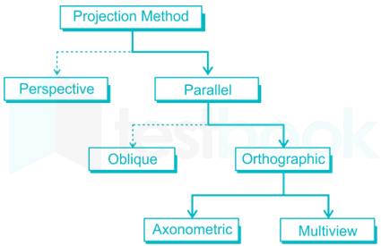
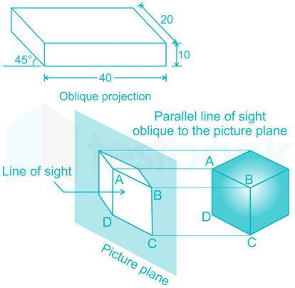
In Oblique projection, projectors from an object are parallel to each other and _________ to the plane of projection.
- Inclined
- Perpendicular
- Parallel
- Cross
Answer (Detailed Solution Below)
Option 1 : Inclined
Concept:
In oblique projection, the object is aligned such that one face (front face) is parallel to the projection plane.
In such projection, the projectors are not perpendicular to the plane of projection rather inclined to the plane of projection at 30˚, 45˚ or 60˚.
Here oblique axis is called as receding axis. In oblique projection, projectors from various points on the object are down parallel to each other and inclined to the plane of projection.
Which of the following views provide clear information of internal features of a part?
- Pictorial views
- Section views
- Oblique views
- Auxiliary views
Answer (Detailed Solution Below)
Option 2 : Section views
Explanation:
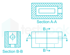
Sectional view:
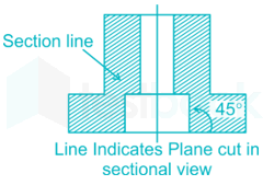
Section lines or cross-hatch lines are added to a section view to indicate the surfaces that are cut by the imaginary cutting plane.
It gives a clear representation of internal features of the part
 Additional Information
Pictorial Projection: A pictorial view gives the information regarding the general shape of the object.
Oblique Projection:These are least realistic. Only one or two faces in oblique projections have true shape and size. There are three types of oblique projections: cabinet, cavalier and general.
Projection of an object shown by three views is known as
- Oblique
- Orthographic
- Isometric
- Perspective
Answer (Detailed Solution Below)
Option 2 : Orthographic
Explanation:
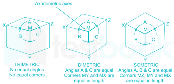
Isometric projection is a type of pictorial projection in which the dimensions along the three axes of the solid are shown in one view and in true size.
Orthographic projection:
- The projection or view obtained on a plane of projection when the projectors are parallel to each other but perpendicular to the plane of projection is known as orthographic projection.
-
- The following two types of orthographic projection are used in engineering practice: (1) First Angle Projection (2) Third Angle Projection
- The front view reveals the two dimensions, namely the length and the height of an object.
- The top view reveals the length and the other dimension (i.e., the width of the object).
- The side view reveals the height/depth and the width of the object (i.e., the length of the object).
- Thus the orthographic view represents the projection of an object by three views.
In computer aided drafting practice, an arc is defined by
- Two end points only
- Center and radius
- Radius and one end point
- Two end points and center
Answer (Detailed Solution Below)
Option 4 : Two end points and center
Concept:
An arc can be created by
- Specifying three points
- Start point, center, and endpoint
- Start point, center, and an included angle
- Start point, endpoint, and a radius etc
The exact value of R.F. on an isometric scale is
- 0.815
- 0.8165
- (2/3)1/2
- 9/11
Answer (Detailed Solution Below)
Option 3 : (2/3)1/2
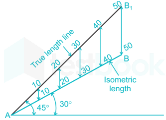
Representation Factor (R. F)
\({\rm{R}}.{\rm{F}} = {\rm{}}\frac{{{\rm{Length\;of\;object\;on\;drawing}}}}{{{\rm{Actual\;length\;of\;the\;object}}}} = \frac{{\cos 45^\circ }}{{\cos 30^\circ }} = \frac{{1/\sqrt 2 }}{{\sqrt 3 /2}} = \sqrt {\frac{2}{3}} \)
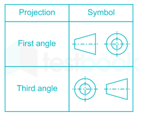
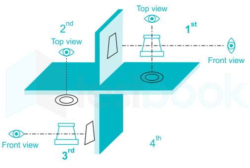
 Symbol in a drawing represents
-
Perspective projection
- Third angle projection
- First angle projection
- Oblique projection
Answer (Detailed Solution Below)
Option 3 : First angle projection
Explanation:
| First angle projection | Third-angle projection |
| Object is kept in the first quadrant | An object is assumed to be kept in the third quadrant |
| Object lies between the observer and the plane of the projection | A plane of projection lies between the observer and the object |
| The plane of projection is assumed to be Non-transparent | The plane of projection is assumed to be transparent. |
| Front (elevation) view is drawn above the XY line | Front (elevation) view is drawn below the XY line |
| Top (plan) view is drawn below the XY line | Top (plan) view is drawn above the XY line |
| Left view is projected on the right plane and vice versa | Left view is projected on the left plane itself |
| Followed in India, European countries | Followed in the USA |
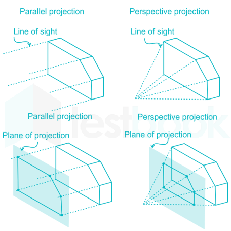
Perspective Projection: The type of pictorial projection in whichall the projectors converge or meet at a point is known as PERSPECTIVE PROJECTION. Perspective drawing has been used by artists and is still used to illustrate the three-dimensional figure. It does not represent the actual size of the object but gives the general outlook.
Oblique Projection: The type of pictorial projection inwhich one face of the object is parallel to the plane of projection and adjacent face is inclined at an angle of 45° to the plane of projection is known as OBLIQUE PROJECTION.
The standard size of drawing board of designation D1 is (in mm)
- 1000 × 700 × 25
- 100 × 75 × 25
- 1500 × 750 × 25
- 1500 × 700 × 25
Answer (Detailed Solution Below)
Option 1 : 1000 × 700 × 25
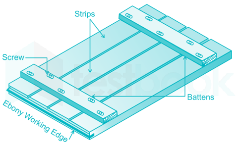
- The drawing board is required to provide a flat surface
- The surface must be smooth and soft so that a pencil can easily draw lines
- It should be free from bumps or holes
- It isrectangularandis made up ofwell-seasoned softwood strips (such as pine, fir, oak or kail) about 25 mm thick of masonite glued together at the bottom
- Two battens are provided to prevent warping and permit expansion or contraction due to change in the atmosphere
- One of the shorter edges of the drawing board is provided with 'ebony edge' on which stock of the T square slides
| S. No | Designation | Size in mm Length × Width × Thickness | To be used with sheet sizes |
| 1. | D0 | 1500 × 1000 × 25 | A0 |
| 2. | D1 | 1000 × 700 × 25 | A1 |
| 3. | D2 | 700 × 500 × 15 | A2 |
| 4. | D3 | 500 × 350 × 15 | A3 |
The Length : Width in case of an arrow head is
- 1 : 1
- 2 : 1
- 3 : 1
- 4 : 1
Answer (Detailed Solution Below)
Option 3 : 3 : 1
Explanation:
Dimension line terminations: The dimension line will have terminations in the form of arrowheads or oblique strokes.
Arrow head:An arrowhead is placed at each end of a dimension line. Its pointed end touches an outline and extension line or center line. The arrow head may be open, closed or closed an filled in open type arrowhead is preferred for fast execution.
Note:
- Thelength of the arrowheadis approximately3 times the width.
- The size of the arrowhead should be proportional to the thickness of the outline.

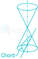
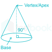
A cone resting on its base in horizontal plane (HP) is cut by a plane inclined to the axis and parallel to one of its generators, the sectional view will be
- Ellipse
- Parabola
- Hyperbola
- Circle
Answer (Detailed Solution Below)
Option 2 : Parabola
Explanation:
Geometrical properties of cone:
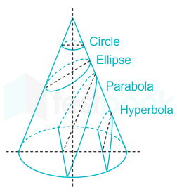
A cone on its base in the horizontal plane (HP) and all generators is cut by plane:
- Inclined to the axis of a cone (more than the angle between slant and cone axis) → Ellipse section will form
- Inclined to the axis of a cone (less than the angle between slant and cone axis) → Hyperbola section will form
- Parallel to the generators (equal the angle between slant and cone axis) → Parabolasection will form
- Parallel to the horizontal plane (perpendicular to the cone axis) → Circular section will form
The internal angle of regular pentagon is __________ degree.
- 72
- 108
- 120
- 150
Answer (Detailed Solution Below)
Option 2 : 108
Internal Angle and External Angle can be seen in the diagram below.
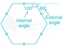
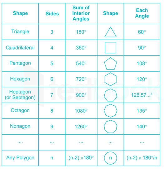
The internal angle of regular hexagon is ______ degree.
- 72
- 108
- 120
- 150
Answer (Detailed Solution Below)
Option 3 : 120
In a rectangular hyperbola, if a curve is traced out by a point moving in such a way that the product of its distances from two fixed lines at right angles to each other is a constant, then those fixed lines are called
- asymptotes
- intercepts
- holes
- limits
Answer (Detailed Solution Below)
Option 1 : asymptotes
Rectangular Hyperbola:
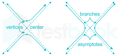
- If in a hyperbola the length of the transverse axis 2a is equal to the length of the conjugate axis 2b, the hyperbola is called a rectangular hyperbola.
- x2− y2= a2 is the general form of rectangular hyperbola. If the asymptotes are x and y axis, then the equation is xy = c2
- The rectangular hyperbola is the hyperbola for which the axes (or asymptotes) are perpendicular, or witheccentricity √2
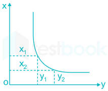
Asymptotes are fixed lines or tangents of rectangular hyperbola, which meets at infinity. If a curve is traced out by a point moving in such a way that the product of its distances from two fixed lines at right angles to each other is a constant.
Here, xy = Constant
Equation of asymptotes is given by,\(y=\pm \frac{b}{a}x\)
Intercepts is the y-value of the point where it crosses the y-axis. In the x-y plane of hyperbola, you will have either x-intercept or y-intercept but never both. If the origin of coordinates is at the centre of hyperbola, the intercepts will be zero.
The line passing through the focus and perpendicular to the directrix is called
- axis
- vertex
- eccentricity
- conic
Answer (Detailed Solution Below)
Option 1 : axis
Concept:
Hyperbola:The locus of a point which moves such that its distance from a fixed point and a fixed straight line is always greater than one (Eccentricity = e > 1)
Equation of hyperbola:\(\frac{{{{\rm{x}}^2}}}{{{{\rm{a}}^2}}} - \frac{{{{\rm{y}}^2}}}{{{{\rm{b}}^2}}} = 1{\rm{\;}},{\rm{\;a}} > {\rm{b}}\)
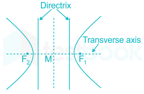
The two lines parallel to the minor axis are calledthe directrix.
The straight line passing through the focus and perpendicular to the directrix is known as transverse axis.
Eccentricity is the ratio of distance from any point from the graph to focus and directrix. A circle has an eccentricity of zero, so the eccentricity shows you how "un-circular" the curve is. Bigger eccentricities are less curved.
Eccentricity of hyperbola =\(\sqrt {1 + \left( {\frac{{{{\rm{b}}^2}}}{{{{\rm{a}}^2}}}} \right)} \)
Different values of eccentricity make different curves:
Ateccentricity = 0 we get acircle
for0 < eccentricity < 1 we get anellipse
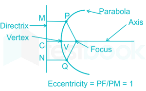
foreccentricity = 1 we get aparabola
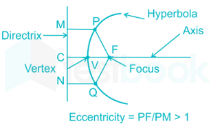
foreccentricity > 1 we get ahyperbola
forinfinite eccentricity, we get aline
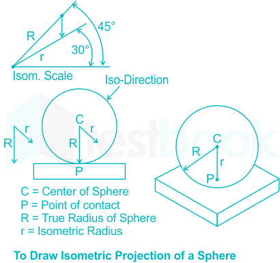
Isometric projection of a sphere is
- Circle
- Ellipse
- Hyperbola
- Parabola
Answer (Detailed Solution Below)
Option 1 : Circle
Explanation:
- In the case of isometric projection, three-dimensional objects are represented visually in two dimensions in technical and engineering drawing.
- An isometric view of an object can be obtained by choosing the viewing direction such that the angles between the projections of the x, y, and z axes are all the same, or 120°.
The isometric projection of a sphere is a circle.
- Other options like the ellipse, hyperbola, and parabola are called conic sections as they are obtained from the sections of a cone at various conditions as shown below-
Additional Information
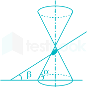
ELLIPSE:
- To get an ellipse the conditions are-
-
 β < α
β < α - The cutting plane should pass through all generators.
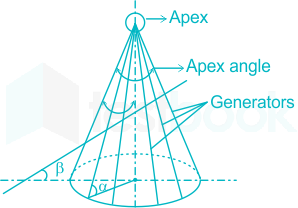
PARABOLA:
- To get a parabola the conditions are-
- β = α
- The cutting plane should be parallel to the generators.
HYPERBOLA:
- To get a parabola the conditions are-
- β > α

The widely employed computer architecture for CAD/CAM application
- Mainframe-based system
- Minicomputer-based system
- Microcomputer-based system
- Workstation-based system
Answer (Detailed Solution Below)
Option 4 : Workstation-based system
Mainframe is a very large in size and expensive computer capable of supporting thousands of users simultaneously. Mainframe executes many programs concurrently.
Minicomputer is a midsize computer. A minicomputer is a multi-processing system capable of supporting up to 250 users simultaneously. A minicomputer is a computer of a size intermediate between a microcomputer and a mainframe.
A microcomputer is a complete computer on a smaller scale and is generally a synonym for, personal computer or PC, a computer designed for an individual.
Workstation is a computer used for engineering applications such as Computer Aided Design/Computer Aided Manufacturing (CAD/CAM), desktop publishing, software development, and other types of applications, which require a moderate amount of computing power and relatively high quality graphics capabilities.
CAD is the use of computer technology for design and design documentation. CAD/CAM applications are used to both design a product and program manufacturing processes, specifically, CNC machining. CAM software uses the models and assemblies created in CAD software to generate tool paths that drive the machines that turn the designs into physical parts.
Curve generated by a fixed point on the circumference of a circle which rolls without slipping along a fixed straight line.
- Involute
- Cycloid
- Spiral
- Helix
Answer (Detailed Solution Below)
Option 2 : Cycloid
There are different Engineering Curves:
| Coneis a surface generated by making a straight line keeping one of its end fixed and other end making a closed curve. | |
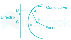
| Conics: The locus of point moves in a plane in such a way that the ratio of its distance from a fixed point (focus) to a fixed straight line (Directrix) is always constant. PF/PM = Const | |
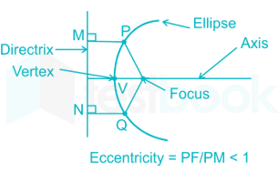
| Ellipse is the locus of a point which moves in a plane so that the ratio of its distance from a fixed point (focus) and a fixed straight line (Directrix) is a constant and less than 1. PF/PM < 1 | |
| Parabola is the locus of a point, which moves in a plane so that its distance from a fixed point (focus) and a fixed straight line (directrix) are always equal. PF/PM = 1 | |
| Hyperbola is the locus of a point which moves in a plane so that the ratio of its distances from a fixed point (focus) and a fixed straight line (directrix) is constant and greater than one. | |
| Cycloidal group of curves: When one curve rolls over another curve without slipping or sliding, the path of any point of the rolling curve is called asRoulette. When the rolling curve is a circle and the curve on which it rolls is a straight line or a circle, we get cycloidal groups of a curve. | |
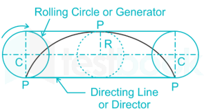
| A cycloid is a locus of a point on the circumference of a rolling circle (generator), which rolls without slipping or sliding along a fixed straight line or a directing line. | |
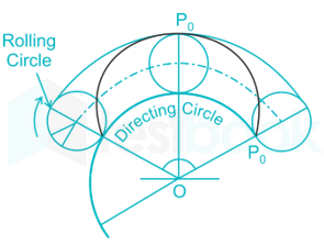
| Epicycloid is a locus of a point on the circumference of a rolling circle (generator), which rolls without slipping or sliding outside another circle called directing circle. | |
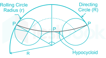
| Hypocycloid is a locus of a point (P) on the circumference of a rolling circle (generator), which rolls without slipping or sliding inside another circle called directing circle. | |
| A trochoid is a locus of a point inside/outside the circumference of a rolling circle, which rolls without slipping or sliding along a fixed straight line or a fixed circle. | |
In the third angle projection, the object is imagined to be placed
- Below H.P and behind V.P.
- Below H.P and infront of V.P.
- Above H.P and behind V.P.
- Above H.P and infront of V.P.
Answer (Detailed Solution Below)
Option 1 : Below H.P and behind V.P.
Explanation:
The orthographic projection system is used to represent a 3D object in a 2D plane. The orthographic projection system utilizes parallel lines, to project 3D object views onto a 2D plane. According to the rule of orthographic projection. To draw a projection view of a 3D object on a 2D Plane. The horizontal plane is rotated in the clockwise direction.
Types of Orthographic projection systems are first angle and third angle projection.
1. First Angle Projection:
In the first angle projection, the object is placed in the 1st quadrant. The object is positioned at the front of a vertical plane and top of the horizontal plane. First angle projection is widely used in India and European countries. The object is placed between the observer and projection planes. The plane of projection is taken solid in 1st angle projection.
Symbol –

2. Third Angle Projection:
In the third angle projection, the object is placed in the third quadrant. The object is placed behind the vertical planes and bottom of the horizontal plane. Third angle projection is widely used in the United States. The projection planes come between the object and the observer. The plane of projection is taken as transparent in 3rd angle projection.
Symbol –

Additional Information
Comparison between First angle and the Third angle projection
| FIRST ANGLE PROJECTION | THIRD ANGLE PROJECTION |
| The object is placed in the first quadrant. | The object is placed in the third quadrant. |
| The object is placed between the plane of projection and observer. | The plane of projection is placed between the object and the observer. |
| The plane of projection is opaque. | The plane of projection is transparent. |
| The front view is at the top of the horizontal axis. | Front view at the bottom of the horizontal axis. |
| Top view at the bottom of the horizontal axis. | Top view at the top of the horizontal axis. |
| The right view is on the left side of the vertical axis. | The right view is on the right side of the vertical axis. |
| The left view is on the right side of the vertical axis. | The left view is on the left side of the vertical axis. |
| It is widely used in Europe, India, Canada | It is widely used in the United State and Australia. |
Engineering Drawing Multiple Choice Questions Pdf Download in Hindi
Source: https://testbook.com/objective-questions/mcq-on-engineering-drawing--5eea6a1439140f30f369f2cd